FSG Autonomy: Creating a track with boundary defined by cones
Video example of this process
Introduction
Tracks in Formula Student competitions are defined by a boundary of two tone cones. When working on a simulated environment it might be tempting to create a custom track by placing cones manually in a 3d environment, but we soon find out that it is very difficult to maintain correct spacing between cones and create desired features. Turns out, we can create a perfect 2.5d track in... 2d manipulation tools.
Here is how.
Tooling
- Powershell - cause I am used to XML manipulation in it. You are welcome to try to rewrite my logic in Python or whatever that can reliably transpile xml
- Inkscape - Main actor of this process
- VSCode/vim - any text manipulation tool you feel comfortable in
Data to prepare
- Top-view image of the track. Satellite images are closest to an orthographic projection. Highly recommended.
- Desired cone spacing. You probably want to match what is described in FSG rulebooks.
The process
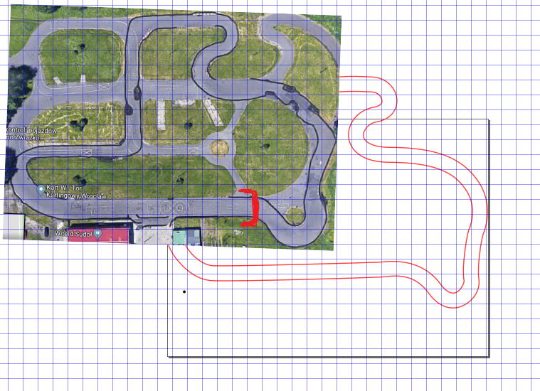
1.Setup canvas
- Go to File->Document Properties->Grids and set Spacing to desired track width in meters + Major Grid line every "1"
- Download image of your track and import it into inkscape
- Align center of the track with top-left corner of the canvas
- Resize the image, so a single grid space matches track-width
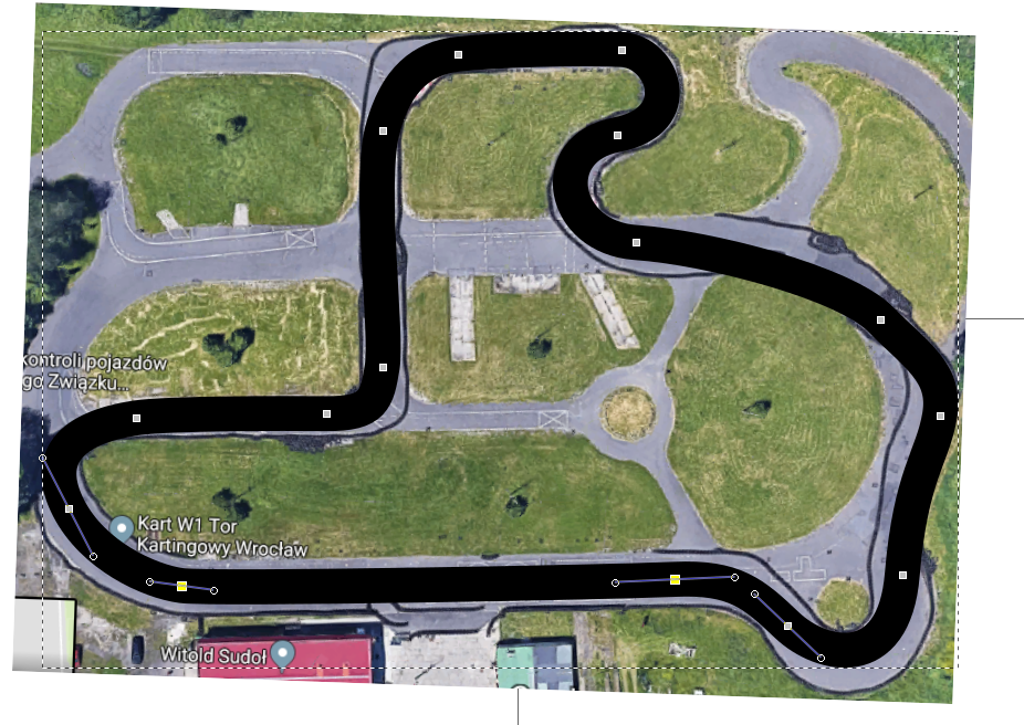
2.Trace the track
- Make sure that the Layer you are working on has no transform on it (through XML Editor)
- Trace through middle of the desired track with bezier-curves
- Adjust stroke width of the line to track width
3.Define track boundaries
- Select the curve and select Path->Stroke to Path
- Now again Path->Break Apart
- Select each of the created curves, disable their Fill and enable a tight Stroke
4.Create cone placeholder
- Create a small circle representing our cone
- Select Path->Object to path on the circle
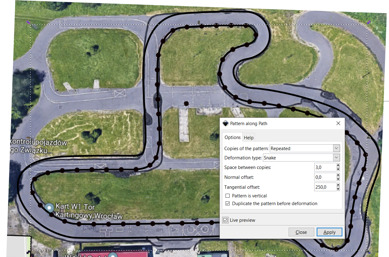
5.Create pattern along the lines
- Select our circle, then Shift select one of the lines
- Go to Extensions->Generate from path->Pattern along path
- Set Repeated, Snake and Space between copies to desired value (it will match to meters in Gazebo)
- Check your results with live preview or Apply
6.Separate cones into individual objects
- Create layers for inside and outside cones
- Move the now created "path" with cones to their own layers
- Select them and Path->Break Apart, now the Layers are filled with their cones
7.Convert cones from path to object, so they have center position in their description (x, y)
- Open XML editor or Objects menu (XML editor is preferable)
- Now select first cone and press Alt+I on your keyboard (It does: Object->Pattern->Objects to pattern)
- Now we have to do this for all cones individually, but in XML editor you can click in one place and do the Alt+I for quick result
8.Make sure once again, that none of the layers have transform on them (XML editor)
9.Convert cones into SDF format
- Save the SVG into easy to reach place
- Modify the contents in your favorite text editor into a pattern like in the examplary file.
- Pass the file through Powershell script
Resources
This exact guide and all the required resources can be found on GitHub
GitHub - HighPriest/SvgGazeboCones: Description of a process of translating a race track traced with bezier-curves into evenly spaced cones ready for Gazebo.
Description of a process of translating a race track traced with bezier-curves into evenly spaced cones ready for Gazebo. - GitHub - HighPriest/SvgGazeboCones: Description of a process of translati…
 HighPriest